



Other Blog


































MPPT stands for Maximum Power Point Tracking. It is an operating method that continuously searches for the point at which a solar panel produces the highest power under the current irradiance and temperature conditions and keeps the panel operating at that point. When used in charge controllers, it converts excess panel voltage into charging current, providing a noticeable gain compared with PWM devices. The difference can reach up to thirty percent at low temperatures and with high-voltage panel strings.
What Is MPPT?
MPPT is an electronic tracking method designed to keep the power produced by a solar panel at the highest possible level. It appears in two different places: inside the charge controller in battery-based systems and in the input channels of the inverter .
The device contains a DC-DC converter. This converter makes the panel operating voltage independent of the voltage required by the battery. While the panel continues to operate at its efficient point, for example at 32 volts, the device reduces this voltage to the 14 volts required by the battery. Because power is conserved, the reduction in voltage is converted into additional current.
A simple example: a panel producing 32 volts and 9 amps delivers approximately 288 watts of power. The device transfers this power to the battery at about 14 volts / 20 amps. The panel remains at its optimum operating point while the battery receives the voltage it needs. The only loss is the small efficiency loss that occurs during conversion.
What Is the Maximum Power Point (MPP) and How Is It Found?

A solar panel does not have to operate at a single voltage; it can operate at any point between zero and its open-circuit voltage. However, it does not produce the same power at every point. There is one point at which the product of voltage and current is highest, and this is called the maximum power point (MPP).
The panel label includes the values that describe this point:
| Abbreviation | Name | What it indicates |
|---|---|---|
| Voc | Open-circuit voltage | The highest voltage measured when no load is connected; current is zero |
| Isc | Short-circuit current | The highest current flowing when the terminals are shorted; voltage is zero |
| Vmp | Maximum power voltage | The voltage at which the panel produces its maximum power; it is lower than Voc |
| Imp | Maximum power current | The current value at the same operating point |
| Pmax | Rated power | The product of Vmp and Imp; the panel’s rated nameplate power |
The critical detail is that these values are measured under laboratory conditions and do not remain constant in the field. The MPP continuously shifts throughout the day. When irradiance decreases, current drops; when cell temperature increases, voltage drops. Passing clouds, morning and evening hours, winter cold and the angle at which the panels are installed continuously shift this point. The fact that panels continue generating even in overcast weather, means that the MPP has shifted to a much lower power level.
For this reason, an MPPT device does not perform a one-time measurement. It changes the input voltage in small steps, measures the resulting power and continues moving in the direction in which power increases. When power begins to decrease, it reverses direction. Because this scan is repeated several times per second, the device can identify the new peak point within a few seconds as conditions change.
How Does a PWM Charge Controller Work?
PWM (Pulse Width Modulation) devices operate on a much simpler principle. An electronic switch is located between the panel and the battery, and this switch rapidly opens and closes to regulate the current flowing to the battery. As the battery fills, the pulse duration becomes shorter and the charging current decreases.
However, this design does not include a converter. While the switch is closed, the panel and battery are directly connected and the panel voltage is pulled down to the battery voltage. In other words, the panel is forced to operate not at its own Vmp value but at the battery’s current voltage.
In numerical terms, a panel designed for a 12-volt system typically has a Vmp of around 17–18 volts, while the battery charging voltage is in the 13–14 volt range. A PWM device pulls the panel voltage down to 14 volts while the current remains unchanged. The roughly 4-volt difference is lost without being used. This corresponds to about one quarter of the power that could otherwise be obtained from the panel.
MPPT vs. PWM Comparison
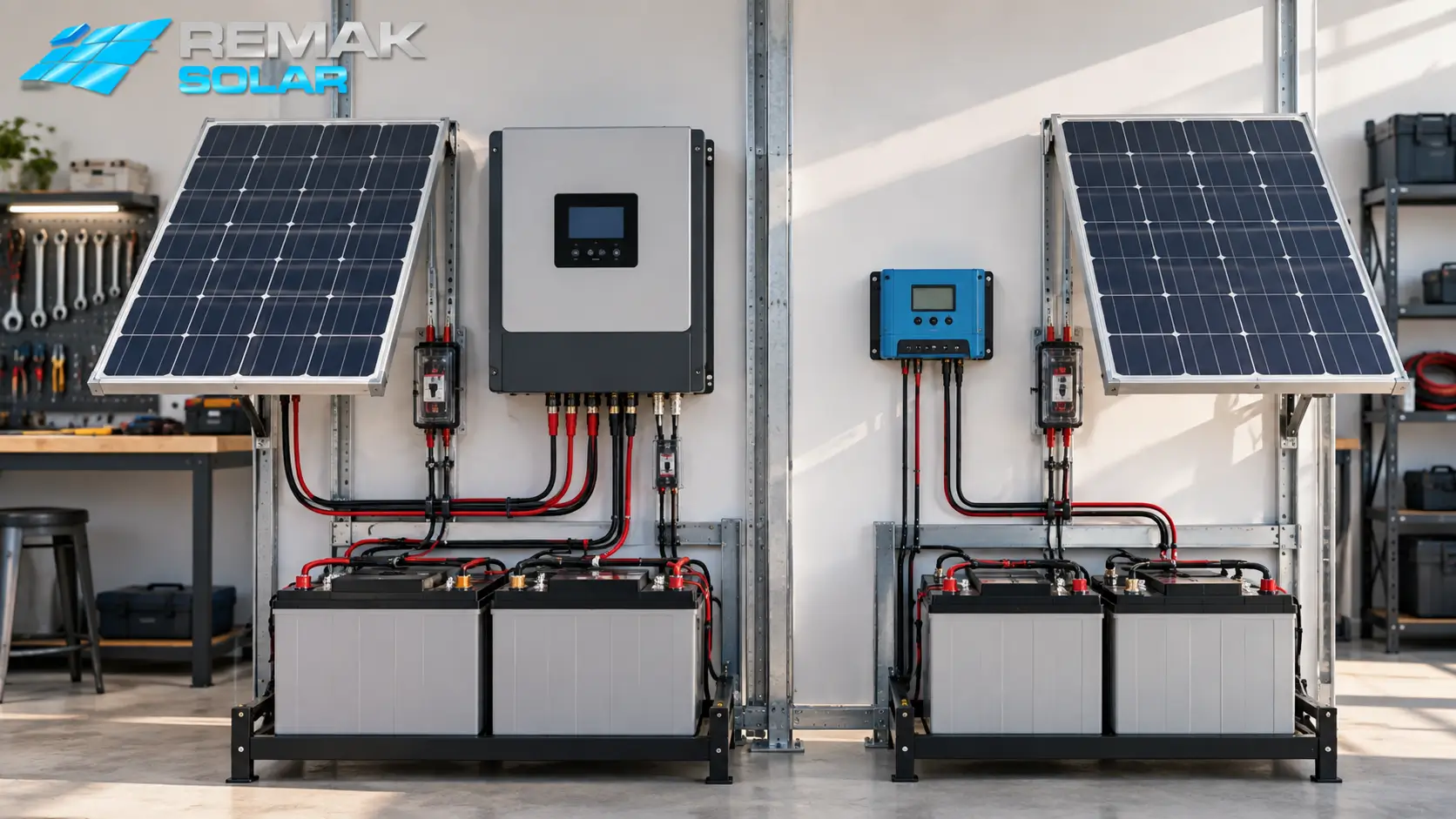
| Comparison | MPPT | PWM |
|---|---|---|
| Operating principle | Converts voltage into current through a DC-DC converter | Regulates current by switching; does not perform voltage conversion |
| Efficiency obtained from the panel | 95%–99%; depending on conditions, 10–30% gain compared with PWM | Around 70%–80%; losses correspond to the voltage difference |
| Panel-to-battery voltage compatibility | Panel voltage can be higher than battery voltage and series connections are possible | Panel and battery voltages must be close to each other |
| Cold-weather performance | Converts the increased panel voltage into usable gain | The increased voltage is completely lost |
| Cable cross-section requirement | Higher voltage means lower current, so a smaller cable cross-section is sufficient | Lower voltage means higher current, so a larger cable cross-section is required |
| Suitable system size | 170 W and above; multi-panel systems | Small systems up to a few hundred watts |
| Cost | Significantly higher at the same current rating | Low; simple circuit design |
| Physical design | Larger enclosure; requires heat-sink fins | Small and lightweight |
Which One Should Be Used in Which System?
The decision depends on two questions: the system power and the ratio of panel voltage to battery voltage.
When PWM is sufficient. PWM is a reasonable solution when total panel power is below a few hundred watts, the panel is designed to match the battery voltage directly (such as a 36-cell panel for a 12-volt battery), and the installation is in a warm region. Caravan lighting, camera systems, garden applications and small boat systems fit this description. At this scale, the gain provided by MPPT may not justify the price difference.
When MPPT is required. MPPT becomes necessary when panel power exceeds a few hundred watts, when panels are connected in series to produce high voltage, when the installation is in a cold region, or when the distance between the panel and battery is long. Solar irrigation systems, farm applications, base stations and off-grid homes fall into this category.
The cold-weather factor is often overlooked. Panel voltage rises at low temperatures; on winter mornings, the Vmp value can increase noticeably above the nameplate value. MPPT converts this increase directly into charging current, whereas it is entirely lost with a PWM device. The difference between the two technologies is greatest in high-altitude and cold regions.
Battery selection affects service life just as much as device selection; when designing the system as a whole, we recommend evaluating the types of solar batteries and how energy is stored together.
Sizing an MPPT Charge Controller
Sizing is based on two limits: the maximum input voltage the device can handle and the maximum output current it can provide.
Output current calculation. The required controller current rating is found by dividing the total panel power by the battery system voltage:
Required current (A) = Total panel power (W) ÷ Battery system voltage (V)
For example, with 1,000 W of panel power and a 24 V battery bank, 1,000 ÷ 24 ≈ 42 amps. After adding a safety margin, a 50-amp controller is selected. When the same panel power is connected to a 48 V system, the requirement falls to 21 amps; this is why increasing system voltage can reduce controller cost.
| Total panel power | 12 V system | 24 V system | 48 V system |
|---|---|---|---|
| 500 W | ~42 A | ~21 A | ~10 A |
| 1.000 W | ~83 A | ~42 A | ~21 A |
| 2.000 W | Not recommended | ~83 A | ~42 A |
| 3.000 W | Not recommended | ~125 A | ~63 A |
Input voltage check. If this step is skipped, the device can be permanently damaged. The total open-circuit voltage (Voc) of panels connected in series must remain below the controller’s maximum input voltage. The calculation should use the Voc corrected for the region’s lowest winter temperature rather than the nameplate value, because voltage rises in cold weather. A string that operates without problems on a summer day can damage the controller on a winter morning precisely when this correction has not been made.
For planning the number of panels and total system power, you can use our article explaining how much energy a solar panel produces and our solar energy calculation tool.
Looking for the Right Solar Energy Solution for Your Project?
Get a free site assessment and quotation from our expert team for solar tracking systems and fixed-panel installations tailored to your land, factory or roof.
Frequently Asked Questions About MPPT and Charge Controllers
Can a solar panel be connected directly to a battery without a charge controller?
It should not be connected directly. Without a charge controller, the panel continues sending energy even after the battery is full; this can cause overcharging, electrolyte loss, case swelling and reduced battery life. Reverse current through the panel at night may also discharge the battery. Direct connection is acceptable only for very small maintenance/trickle-charge panels relative to the battery capacity, provided that a blocking diode is installed.
During installation, should the panel or the battery be connected first?
Connect the battery first. Most MPPT devices detect the system voltage they will operate at (12 V, 24 V or 48 V) from the battery. If the panel is connected first, the device may identify the system voltage incorrectly or fail to start. The correct sequence is battery first, then panel and finally the load; disconnection is carried out in the reverse order.
Should the panels be connected in series or in parallel?
With MPPT devices, a series connection is advantageous in most cases. Series wiring increases voltage while keeping current constant, which allows a smaller cable cross-section and reduces line losses. However, if one panel in a series string is shaded, the entire string is affected. In sites with shading sources, parallel connection or splitting groups across separate inputs is safer. With PWM devices, series connection is generally not possible, so panels are connected in parallel.
Can I connect panels of different power ratings and brands to the same charge controller?
It is technically possible, but it causes efficiency losses. In a series connection, all panels in the string are limited to the current of the lowest-current panel; in a parallel connection, panels with different voltages pull one another down. If mixed panels must be used, the best solution is to group panels with the same characteristics and connect those groups to separate MPPT inputs or separate controllers.
Does an MPPT charge controller discharge the battery at night?
The controller’s own electronics draw a very small standby current, typically in the milliamp range and negligible compared with battery capacity. Reverse current that could flow toward the panel is blocked by the controller’s internal blocking circuit. If significant discharge is observed at night, the cause is usually not the controller but a continuously operating load connected to the system or an aging battery.
Where should an MPPT charge controller be installed?
The controller should be installed as close to the battery as possible, because the line between the battery and controller carries high current and losses increase with distance. The installation location should be dry, shaded and well ventilated. Heat-sink fins must not be covered, and the controller should not be mounted directly above the battery because gases released by lead-acid batteries can cause corrosion on the electronic circuit board.
Do Comment