

Other Blog








The solar panel inverter is, in a solar power plant (PV) investment, the component that should be discussed the most after the panels, yet is often discussed the least. No matter how high-quality the panels are, if the energy they produce passes through an incorrectly sized converter, the result is a loss in the field. Following our article in which we discussed the operating principle and types of the device in detail, what is an inverter, in this guide we focus entirely on the selection side: we will examine step by step the criteria you should use to evaluate capacity, DC/AC ratio, number of MPPT inputs, efficiency, protection class, warranty and monitoring.
Why Is Inverter Selection Critical to System Efficiency?
Every kilowatt-hour produced in a solar energy system must pass through the inverter. Therefore, the performance of the device has a direct multiplier effect on the entire system. While a problem in a panel string is usually limited to that string, a loss caused by the inverter affects the entire site.
The field impact of an incorrect selection appears in three ways. The first is clipping loss: a device selected with insufficient capacity cannot transfer peak production at midday to its output and cuts off the excess. The second is partial-load loss: a device selected larger than necessary operates far below its capacity throughout the day, and because efficiency drops at low load, annual production remains below expectations. The third is downtime: if a device from a brand with a weak service network fails and has to wait for spare parts, the site may remain without production for weeks.
These three items have one thing in common: none of them is noticed on the installation day. They all become visible in the first year's production report. For this reason, selection is an engineering decision that must be made at the quotation stage; correcting it later requires replacing the device.
Inverter Capacity and DC/AC Ratio According to System Power
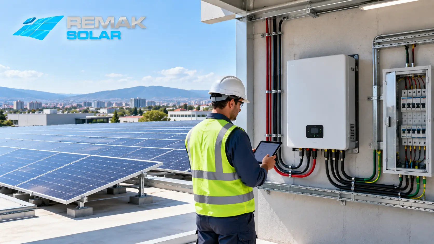
The starting point for selection is the total panel power to be installed. However, a common misconception arises here: it is often assumed that inverter power must be selected exactly equal to panel power. In practice, the situation is different.
Panels deliver their nameplate ratings only under laboratory conditions (1000 W/m² irradiance, 25 °C cell temperature). In the field, these conditions occur during only a very small part of the year. The actual production curve starts low in the morning, rises toward noon and falls again in the evening. Therefore, installed panel power is selected somewhat higher than inverter power. This relationship is called the DC/AC ratio and is calculated with the following formula:
DC/AC ratio = Total panel power (kWp) ÷ Inverter nominal AC power (kW)
For example, if a 10 kW inverter is selected for 12 kWp of panel power, the ratio is 1.2. The correct range for this ratio is not fixed; it varies according to the site's irradiance profile, panel orientation, and whether the system is fixed or tracking.
| Site type | Typical DC/AC ratio | Rationale |
|---|---|---|
| South-facing fixed roof | 1.15 – 1.30 | The production curve forms a sharp peak at midday; moderate oversizing increases annual production without causing significant clipping |
| East-west oriented roof | 1.25 – 1.40 | Because production is spread throughout the day, the peak value is lower, allowing a higher ratio |
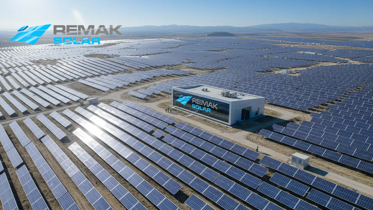
| Ground-mounted fixed system | 1.20 – 1.35 | In high-irradiance sites the ratio is kept closer to the lower limit, while in shaded sites it is moved closer to the upper limit |
| Site with a solar tracking system | 1.10 – 1.25 | Because the production curve remains broad from morning to evening, the peak duration is longer and the ratio is kept lower |
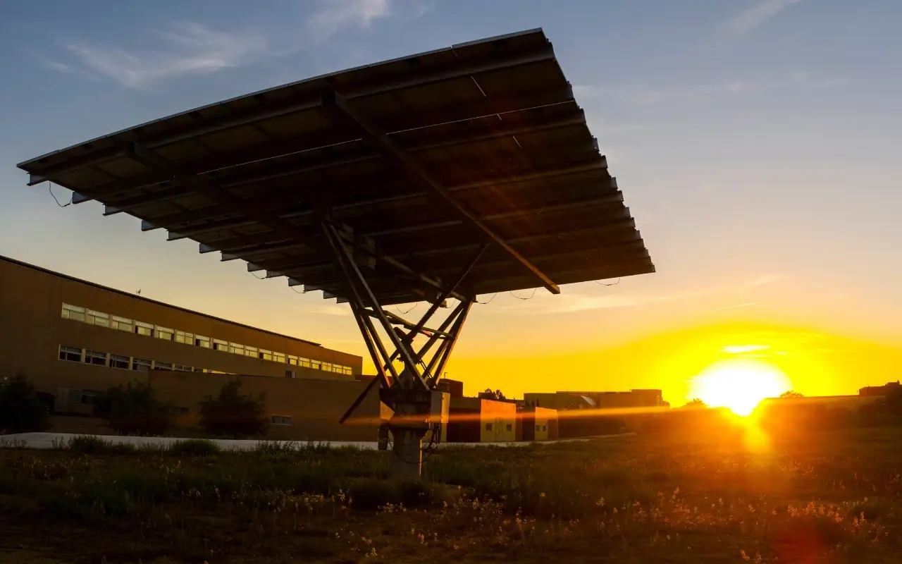
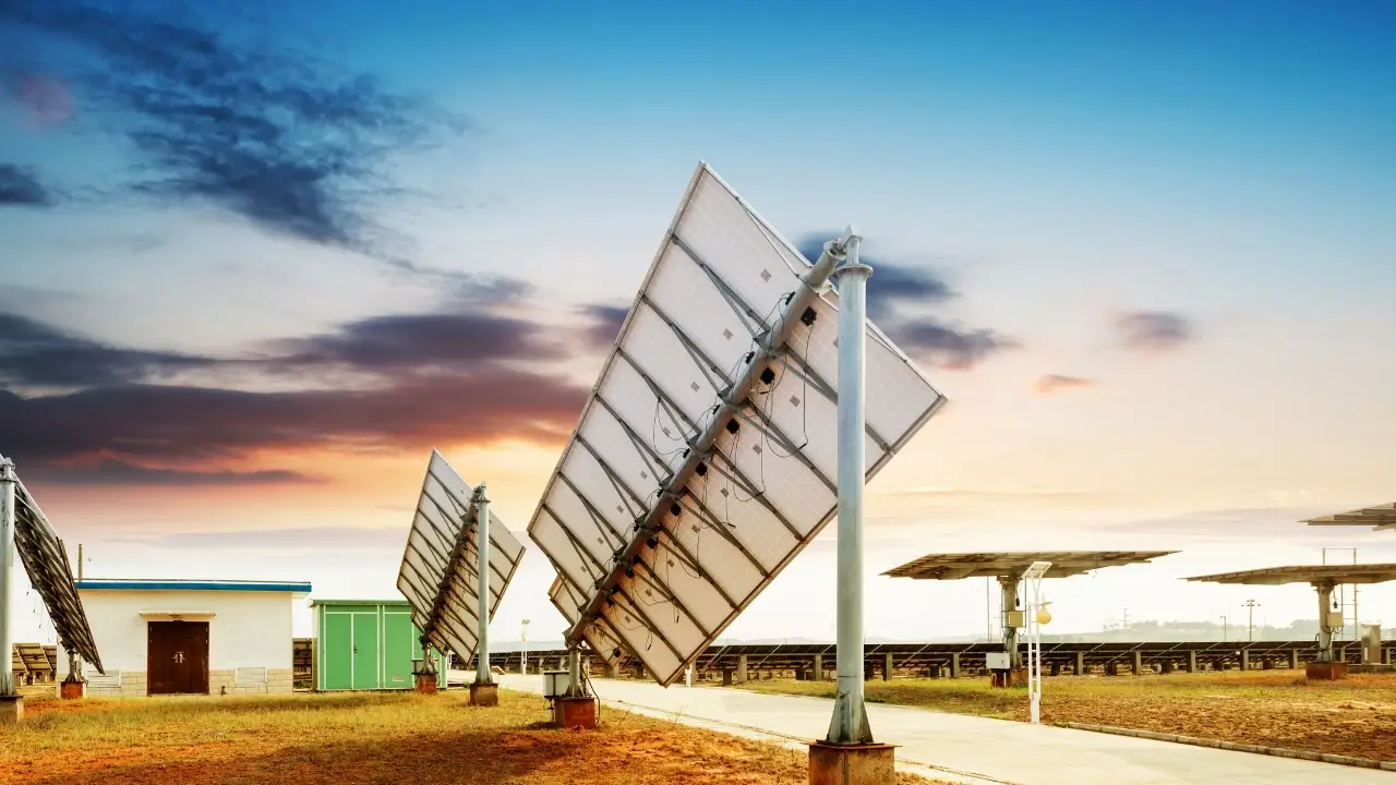
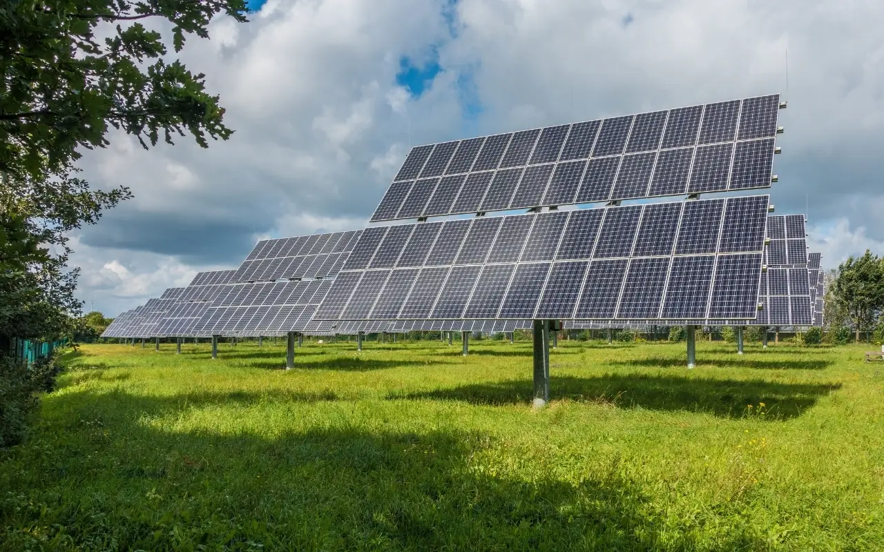
The last row in the table requires particular attention. Solar tracking system On sites where it is used, the panels follow the sun throughout the day, so the production curve forms a broad plateau instead of a sharp peak concentrated around noon. The device operates near its nominal power for a much longer period. A high DC/AC ratio chosen with fixed-system habits can cause hours of clipping around midday on a tracker-equipped site. Therefore, the ratio must be calculated separately for tracking-system projects.
To estimate the annual production of your own system, you can use our solar energy calculation tool and follow the logic behind the calculation in our article how to calculate solar energy .
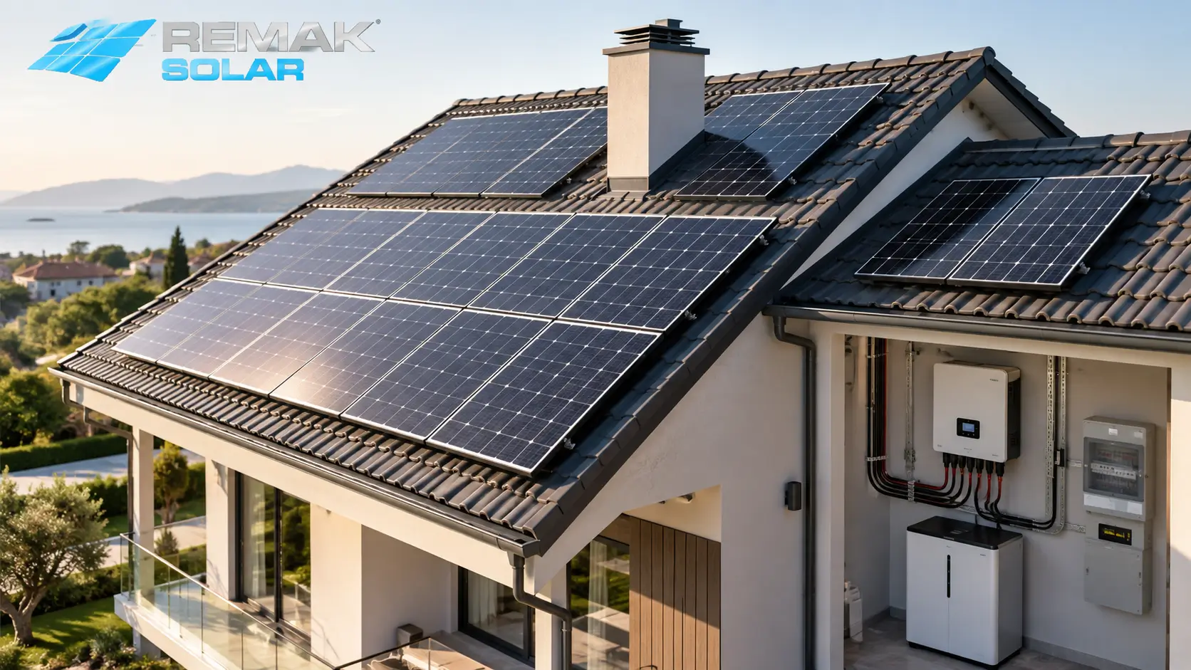
The MPPT input refers to the number of channels through which the inverter can independently manage the panel string. The important point for selection is this: all panels connected to the same MPPT input are forced to operate at a common operating point. In other words, when one panel in that group is shaded, the other panels on the channel are also pulled down.
For this reason, the number of MPPT inputs is determined according to the physical layout of the roof or land. The practical rule is to connect each panel group that behaves differently to a separate input. The main situations that create different behavior are:
- Roof surfaces facing different directions (east and west faces do not peak at the same time)
- Sections with different tilt angles
- Areas shaded by chimneys, elevator towers, trees or neighboring buildings
- Strings containing different numbers of panels and therefore producing different voltages
On a single-orientation, unobstructed roof, two MPPT inputs are usually sufficient. Roofs with irregular lines, multiple orientations or shading sources require three or more inputs. When planning panel placement, how to position solar panels the orientation and tilt criteria in our article also largely determine how many MPPT inputs you will need.
During selection, also remember that each MPPT input has its own current and voltage limits. The number of strings that can be connected to an input is limited by the maximum input current in the device data sheet; even if the number of inputs appears sufficient, the connection plan must be redesigned if the current limit is exceeded.
Efficiency Values: Nominal Efficiency and European Efficiency
The high percentage highlighted in catalogs is usually the nominal (peak) efficiencythat the device reaches only at the ideal load point. The time spent at this point in the field is limited. The main value to look at when comparing devices is the European (Euro) efficiency; this value combines the device's performance at different load levels using a weighted average and provides an indicator much closer to actual annual production. Devices intended for the US market use CEC efficiency, which is calculated with similar logic.
Even if two devices have the same nominal efficiency, there may be a difference of up to half a percentage point between their European efficiencies. This difference shows how well the device performs at low loads and can have a noticeable impact on annual production at sites with long morning and evening periods.
Another factor affecting efficiency is temperature. Each device data sheet includes a threshold after which the device begins to reduce output power at a certain ambient temperature. This is called derating, and in regions where site temperatures exceed 40 °C in summer it translates directly into production loss. When choosing between two devices, checking where the derating threshold begins is more informative than looking only at the efficiency percentage.
Grid-Tied, Off-Grid or Hybrid?
This decision is less about a technical preference than about the purpose for which the system is being installed, and it must be clarified before all other criteria; because when the device type changes, both the capacity calculation and the connection diagram must be redesigned from the beginning.
| Comparison | Grid-tied (on-grid) | Off-grid | Hybrid |
|---|---|---|---|
| Battery requirement | None | Mandatory | Optional, can be added later |
| During a grid outage | Production stops | Unaffected | Supply continues from the battery |
| Excess production | Fed into the grid and offset | Wasted once the battery is full | First to the battery, then to the grid |
| Typical use | Residential and factory roofs, ground-mounted solar power plants | Off-grid farmland, mountain houses, base stations | Facilities sensitive to power outages |
| System complexity | Lowest | Medium, requires battery management | Highest |
Grid-tied systems are the standard choice for rooftop solar power plants and self-consumption projects for factories . On the hybrid side, the economic aspect of the decision depends on how excess production is utilized; on this topic, our article on hourly netting will be a useful guide. For off-grid selection, since battery chemistry determines system life as much as the device itself, we recommend evaluating types of solar energy batteries in advance.
IP Protection Class and Operating Temperature Range
The IP class is a two-digit code indicating the degree to which the device is protected against solid objects and water. The first digit indicates protection against dust and solid objects, while the second indicates the level of protection against water ingress. If the installation location is outdoors, this value is non-negotiable.
| Protection class | Meaning | Suitable installation location |
|---|---|---|
| IP54 | Limited dust protection, resistant to splashing water | Enclosed technical area, garage, electrical room |
| IP65 | Completely dust-tight, resistant to low-pressure water jets | Exterior wall, under-roof area, eave-protected area |
| IP66 | Completely dust-tight, resistant to powerful water jets | Open land, dusty agricultural sites, coastal regions |
The operating temperature range indicates the ambient temperatures at which the device can operate without reducing power. Considering that roof surface temperatures can reach 60 °C during summer under conditions in Türkiye, models with a wide temperature range and a high derating threshold provide a clear advantage. The effect of climate conditions on system efficiency must be taken into account not only on the panel side but also on the inverter side.
A practical note for installation: even if the IP class is high, mounting the device on a wall exposed to direct sunlight creates unnecessary thermal stress. A shaded location with unobstructed air circulation always gives better results.
Warranty Period and Local Service Network
While 25-30 year performance warranties are standard for panels, inverter warranties are generally in the 5-10 year range, and most manufacturers offer paid extensions. This asymmetry raises the possibility that the device will need to be replaced at least once during the system's lifetime; this item should be included from the outset when planning the investment.
More critical than the warranty period itself is access to service. The following questions should be clarified during evaluation:
- Does the brand have an authorized technical service network and spare-parts stock in Türkiye?
- What response time is committed in the event of a failure?
- Does the warranty cover only the device, or are labor and shipping also included?
- Is the manufacturer's market history established enough to support the warranty period?
The last point is more important than it may seem. A ten-year warranty is meaningful only if the manufacturer is still operating ten years later. Especially in megawatt-scale solar power plant projects, having a single device wait for spare parts for weeks can correspond to a serious production loss.
Monitoring Support
Monitoring support was long considered a “nice to have”; today it is a fundamental tool for fault detection. Modern devices transmit data via Wi-Fi, Ethernet, RS485 or a cellular module, and this data is monitored through a web panel or mobile application.
When making a selection, the points to check are: how far back the data history goes, whether measurement is performed at string level or only as a total, whether remote monitoring requires an additional subscription, and whether the system allows data export.
A system that provides string-level measurement makes it possible to diagnose a production drop without going to the site, because it directly shows which section is responsible. In fact, understanding whether the panels are operating is often fastest by comparing strings on the monitoring screen. Soiling, shading or a single-panel failure can be detected on this screen weeks in advance.
Are You Looking for the Right Solar Energy Solution for Your Project?
Get a free site assessment and quotation from our expert team for solar tracking systems and fixed-panel installations tailored to your land, factory or roof.
Frequently Asked Questions About Inverter Selection
Should a single-phase or three-phase inverter be selected?
The determining factor is the facility's existing electricity connection. Homes generally have single-phase service, and single-phase devices are used for systems up to approximately 10 kW. In workplaces, workshops and factories with three-phase service, a three-phase model is preferred; this distributes the load evenly across the phases and prevents voltage-rise problems on a single phase. Although it is technically possible to connect a single-phase device to a facility with three-phase service, it is not recommended because it creates phase imbalance.
Can panels and inverters from different brands be used together?
Yes, they can. Compatibility between a panel and an inverter depends on electrical values, not the brand. The panel string's open-circuit voltage must not exceed the inverter's maximum input voltage, the string current must remain below the input-current limit, and the string voltage must fall within the device's MPPT operating range. As long as these three conditions are met, using different brands does not create a problem. However, it should be remembered that monitoring and optimization features of some brands operate only within their own ecosystem.
What is the difference between transformer-based and transformerless inverters?
In transformer-based models, the DC and AC sides are electrically isolated from each other by a transformer; this design is preferred for certain special grounding requirements and specific panel technologies, but the device is heavier and its efficiency is somewhat lower. Transformerless models do not have this isolation, but they offer higher efficiency and a lighter enclosure. Today, the vast majority of grid-tied systems are built with transformerless devices.
How long should the cable distance between the panels and the inverter be?
There is no absolute upper limit, but as the distance increases, voltage drop on the DC line also increases and directly becomes a loss. The design target is to keep voltage drop on the DC side at around one percent. If a long distance is necessary, increasing the cable cross-section is the solution. For this reason, the inverter is positioned as close as possible to the panel strings while keeping the AC line to the distribution board short.
Will I need to replace the inverter if I add panels later?
It depends on the existing device's input capacity and DC/AC ratio. If the panels to be added remain within the device's maximum DC input power and MPPT current limits, replacement is not required. If these limits are exceeded, there are two options: replace the device with a larger model or install a second inverter for the added section. In projects where future capacity increases are anticipated, selecting a model with some input headroom during the initial installation eliminates additional expense later.
When should the inverter be replaced?
The commonly accepted average service life in the field is 10-15 years, and since panels last much longer, replacing the inverter once during the system's lifetime is considered normal. The replacement decision depends more on behavior than on calendar age: a persistent drop in production under the same irradiance conditions, recurring error codes, frequent self-shutdowns, and increasing fan and cooling problems indicate that it is time for replacement.
Do Comment